NVIS Antenna Addition

Making your own transformers!
Why make your own?
Of all the components we use in ham radio, transformers seem to be one of the greatest mysteries. I started on a mission to learn how to make transformers of the types we use in ham radio, from power line to audio to upper HF (30Mhz) frequencies. I needed it to be something that was reasonably available cost-wise and experience-wise for me and the average home experimenter/ham operator. I decided to write a series of articles about this.
Note: I strongly recomend reading this entire article before starting a transformer project. Here is a link to an Excel spreadsheet that will do most of the design work for you:
The first transformer project:
In today’s world of switching power supplies, conventional power line transformer availability is becoming questionable, and it seems reasonable to start my trip here. This first article is about learning to make line frequency power transformers, but I learned that much of the transformer design process is common to all types of transformers.
In this case I wanted to make a 5-volt 5-amp and ± 15-volt 1-amp bench power supply. I wanted to use linear regulators to eliminate electrical noise. In order to use linear regulators, I needed a transformer to step down my 120V 60Hz line to voltages appropriate for linear regulators for +5 and ±15 outputs.
For the linear regulator inputs, I need 1-volt for the bridge rectifier drop and 3-volts headroom for the regulator to work properly. So, the transformer needs to have one 9-volt winding for the 5-volt 5-amp output, and two 19-volt 1-amp windings for the two 15-volt outputs. I always look for off the shelf parts that can be made to do what I need when designing a new project. I found one stock transformer that would take care of the 9-volt requirement and another stock transformer that would take care of the two 19-volt requirements. Using two transformers would have substantially increased the size and weight of the project, so I decided this was a good opportunity to build my own custom transformer.
This launched my hunt for the supplies and info needed to make this transformer.
Items needed:
Transformer core, bobbin to fit the core, magnet wire, transformer tape, potting compound, and a
winding machine.
Magnetic cores:
I investigated various cores available. After experimenting with some off the shelf ferrite cores, it became clear that they were fine for high frequencies but not for 60 Hertz. I’ll defer ferrite core use to future higher frequency transformer projects.
Silicon steel lamentations have traditionally been used to make 50-60 Hertz transformers. 3% Silicon steel has a higher maximum flux density (B max) than any of the ferrites. The maximum flux density of a core limits it’s power handling capacity. Silicon steel lamentations and transformers are mostly imported from Asia, but silicon steel laminations are still available from several U. S. suppliers on the web.[1][2] I bought 2 ea. thirty-five-pound boxes of EI 100 (1 inch tongue) and 2 ea. fifty-five-pound boxes of I 175 (11.75-inch tongue). These two sizes will cover the range of 25 VA to 500 VA in eight configurations of stack heights.
Bobbins:
I found several sources of bobbins, but the small quantity stock is limited, or is surplus and not every
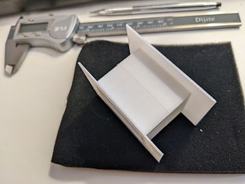
size is available without a large quantity long lead time order.[3][4] I bought several sizes that were available, but finally decided that sometimes it is more practical to 3D print them. I used FreeCAD freeware software to design the bobbin and printed them with PLA (a popular 3D printer material). PLA is usable to 40°C, so it is not suitable for a transformer designed for 40°C rise (standard for small electronic transformers). I expect to use the same design with PETG which is usable to 70° C. This should meet the 40°C rise requirement. I made the bobbins in two parts that join in the center. Then I superglued them together. See Figures 1 and 2.
Wire:
Magnet wire is readily available from online suppliers. I selected polyurethane solderable 155°C wire. It can be soldered with a soldering gun, much easier than scraping off enamel from enameled magnet wire.
NOTE: If you must use enameled wire, it can be stripped with aircraft type gel paint remover, much neater and safer than scraping off the insulation and possibly nicking the wire.
Tape:
3M #56 Yellow Polyester Film Electrical Tape can be purchased online. This is the traditional yellow tape used in small power transformers. It is 1 mil thick polyester, 2.5 mils total with thermosetting adhesive. I bought a ¼ inch and a ½ inch wide roll.
Potting compounds:
Two-part epoxy’s are available online. I haven't been able to find a retail supplier for transformer varnish. Potting is not necessary, biggest advantage of potting is elimination of buzzing of lamentations and windings in normal office environments.
I built a simple winding machine, See Figure 3, but after doing a little preliminary testing, I decided I needed a turns counter. I had trouble keeping track of the turns count while watching the wire to make sure it layers properly, doesn't tangle etc. I found a coil winder with a counter “U.S. Solid Manual Coil Winder NZ-1 Coil Winding Machine w/ Counter” for under $35.00! so I bought one (a little over $50 with shipping).[5] I mounted it on a 2X6 X 16-inch board. See Figure 13
I bought a pair of triangular heavy duty shelf brackets online and mounted them 10 ½ inches apart on another 2X6 X 16-inch board. This board is for the magnet wire spool support. In use, I clamp the two boards to a pair of sawhorses. When not in use they can be easily removed and stored out of the way.
Mandrel:
I cut mandrels as needed for different size bobbins from well-seasoned wood (whatever size is larger than the bobbin hole). I make it slightly smaller than the bobbin hole. Then, I drill a 5 mm hole thru the axis and mill a 1/8” slot across the 5 mm hole on one end to engage with the roll-pin. I slip the mandrels on the axle rod up against the roll-pin on the shaft. I put some tape around the axle on the other side of the mandrel to keep it from slipping away from the roll-pin.
Wire spool support:
I used a 12 inch length of ½ inch EMT (thin wall electrical conduit) in between the two brackets on the wire supply board to hold my spool of magnet wire. I used tractor “Hairpins” through 5/32 inch holes on each end of the EMT conduit to keep it from sliding off the brackets in use. See Figure 4
Transformer calculations
Note: no discussion of magnetic core transformers would be complete without mentioning magnetic core saturation. Core operation at high flux densities too far into the saturation region will cause overheating and eventually failure of the transformer. Here, the primary winding is chosen to be a compromise between core capacity in Volt * Amps and core saturation current at high input voltage. Bmax is the value that is used to determine the saturation of the chosen lamination material. It has a range of values depending on how much saturation current the designer is willing to tolerate. For the 3% silicon steel chosen for this article, I use Bmax of 1.000 to 1.176 Tesla’s as being commonly acceptable Bmax values for these laminations.
The transformer design process starts with selection of the core material and core size. Two factors need attention when selecting core size: It needs to be big enough to accommodate the total winding size and it needs be big enough to dissipate the heat generated by the transformer in full load operation, The winding size will be a function of the core magnetic area and the material’s Bmax. We use the magnetic area and Bmax to determine the number of primary turns required and the full load rating to determine the primary winding wire size. Then we check that this primary will fit into approximately ½ of the available winding window. Once these requirements are satisfied, the rest of the design process is straight forward.
Select lamination size:
Transformer design starts with determination the maximum VA rating of the transformer from the total of the secondary(s) full load voltage and current.
Calculate required Volt*Amperes:
Calculate the volt*ampere (VA) total for the secondary(s). Assuming the transformer’s efficiency is 85%, calculate the Primary VA equal to secondary VA / 0.85.
Now, average the primary and secondary VA’s. We will use this average to select the required lamination:
Select appropriate lamination size and stack height:
Using the average VA, select the lamination from the data supplied by the vendor. For this first transformer we are using M6 29-gauge 3% silicon steel laminations. For 50/60 Hz electronic transformers, you can use the following table for EI-100, EI-175, or EI-300. For other M6 laminations use the chart for selection.
The table N columns are the number of primary turns suggested for a 130V 60Hz line primary. (See fig 7 & 8)
Primary winding: Now that you have selected the lamination and stack size, we need to determine the primary winding. Several steps are required:
-
Select primary wire size:
To select the wire size we need to calculate the primary current: Using the Primary VA calculated above, calculate the primary current:
Primary Amps = Primary VA / Primary voltage.-
For 40C° Rise, calculate Wire Circular Mils Required = 500 X Primary Amps
Using 500 X Primary Amps, determine the primary wire size.
Circular Mils (cmil): See NOTE 1
-
-
Calculate number of Primary turns:
N = Vpri / 4.44*f*A(meters²)*B(Tesla's)
Where:
N = number of primary turns
V = Primary voltage applied (Line Voltage)
f = Frequency
A = Area in Square Meters (Meters² = inch² * 0.0006452)
B = Maximum flux density in Tesla’s (1 Tesla = 64516 Lines/inch² = 10,000Gauss)
NOTE: For M6 lamination material,
B is 1.000 (Conservative) to 1.175(Aggressive) in Tesla's. I have calculated the required number of turns for conservative and aggressive B’s in the table above.-
Determine winding fill and length characteristics:
Now that we know how many turns calculated for the primary, we can check it’s fill and length.-
Calculate the fill:
First calculate the total available winding window area in square mils. The window for a EI lamentation is ½ the tongue width tall and 1-½ the tongue width wide. Using the EI 100 for example, the tongue is one inch wide, so the winding window is ½ inch x 1½ inches. To calculate the area in cmil, we multiply the dimensions in thousands of an inch to get cmil: 500 * 1500 = 750000 cmil. For hand wound transformers, it’s prudent to keep the total fill around 30% or less, and the amount allocated to the primary and secondary(s) should be about equal. Using the previously determined wire size and number of turns, calculate the primary area required in cmil and check to see if it will fit within about 15% or less of the available area. If it won’t fit, you should increase the lamination magnetic area by either increasing the stack height, or choosing a larger lamentation, and re-calculate. No sense in spending all this effort and winding a marginal transformer! -
Calculate length and winding resistance:
Now that we know how many turns calculated for the primary, we can calculate the primary resistance. We need the length of wire to calculate the resistance. Assuming the primary is the first winding, we just need to know how many layers. This can be calculated from the width of the winding window (inside the bobbin) divided by number of turns times the diameter of the wire. Now the length of each turn in the first layer is the core dimensions of the bobbin (tongue width + bobbin thickness and stack thickness + bobbin thickness) If more than one layer is required, just average the length of the first layer and last layer * number of turns to get a reasonable estimate. Look up the “Ohms per 1000 Ft” in the wire table, and find the primary resistance for this length.
-
-
-
Calculate primary voltage drop:
Now that we know the resistance, calculate the voltage drop in the primary from the full load amps calculated above. We use this “PriVDrop” as the effective primary voltage in calculating the secondary turns next.
Secondary winding:
Calculate number of turns, proportional to the turns ratio, with the primary voltage reduced for PriVDrop:
Ns = Np * Vs / (Vpri – PriVDrop)
Calculate resistance and voltage drop adjust turns to bring up to desired output.
Adjusting turns for low voltage winding
One secondary turn might result in too high or too low voltage on the secondary, so it is acceptable to add or remove a few turns on the primary to achieve the desired secondary output voltage.
It’s good practice to check the voltage drop on the secondary(s) using a similar procedure to the primary to see if an adjustment to turns of primary or secondary are needed to compensate.
Example: Build a 120V 60 Hz primary transformer with two 19V @ 1 amp and one 9 v @ 5 amp secondary's:
For this project I need to build a ±15 V @ 1 amp and +5 V @ 5 amp power supply. I need 4 volts RMS headroom on each winding to allow for 1 volt drop in the bridge rectifier and 3 volts headroom for the regulator, hence the 19 volt and 9 volt requirements for the transformer secondaries.
1. Calculate the VA requirements:
a) 19V*1Amp = 19VA for the – 15 volt winding
b) 19V*1Amp = 19VA for the + 15 volt winding
c) 9V*5Amp = 45VA for the + 5 volt winding
=83 VA total required
2. Using the 85% efficiency I get: 83 / 0.85 = 97.65 Input VA required.
3. Select Lamination and stack height:
a) From the chart above, I chose the EI-100, with 2 inch stack, rated at 100 VA.
4. Primary wire size:
The primary full load Amps calculate as 98 VA / 120V = 0.82 amps
Using 500 cmil)/ Amp, I get 500 * 0.82 =410 cmil.
Looking up in my Solid Copper Wire Table, #24 is 404 cmil, #23 is 509 cmil
5. The number of primary turns from the table above is between 322 – 378.
I’m going with 350 as being “Split the difference” between the two.
6. Now, I need to check the fill on my bobbin, this will let me decide if I have enough room for #23.
This bobbin is split with a vertical fin in the middle to separate the primary from the secondaries. The horizontal measurement is 0.667 inches, and the fill height is 0.424 inches.
a) This calculates to 667 mils * 424 mils = 282,808 cmil available and 350 turns * 571 SINGLE COATED cmil for #23 = 199,924 cmil.
100 * (178,500/282,808) = 71 % fill in that side of the bobbin. This is too tight a fill for hand winding, so I’m going with #24.
b) The #24 fill calculates to 350 turns * 454 cmil for #24 = 158,900 cmil.
158,900 / 282,808 = 56% fill which should be more do-able.
I have decided to add primary taps at 315, 350, and 385 turns for line voltages of 108, 120 and 132 Volts 60 Hz
7. Calculate the primary resistance:
The inside dimensions are 1.01 X 2.01 inches and the outside are 1.99 X 3.00.
Averaging them, I get 1.5 X 2.5 approximately. So, each turn will be
1.5 + 2.5 + 1.5 + 2.5 = 8 inches / Turn (average, 6 inches for the first layer, 10 inches for the last layer.
8 * 350 Turns = 2800 inches. 2800 / 12 = 233 feet.
From my wire table, #24 has 25.67 ohms/1000ft. So, 25.67 * 233 / 1000 = 6.00 ohms primary resistance.
8. Calculate the primary voltage drop:
From the primary full load amps = 0.82 * 6.00 ohms primary resistance = 4.92 volts drop.
9. Calculate the secondaries:
a) 9 Volt: Number of turns = 350 * 9/(120 – 4.92) = 27..37 turns, I’ll round up to 28 turns. Wire size 5A * 500 cmil = 2500cmil, #16 is 2,583cmil. I don’t have any #16, so I’ll use two #19’s bifilar wound (1288cmil *2 = 2576cmil is almost exactly the same as 2583 cmil for #16).Using inner dimension of the bobbins sides: 1+2+1+2 = 6 inches per turn * 28 turns = 168 inches / 12 = 14 feet. At 8.05 ohms / 1000 ft., R = 14/1000 * 8.05 = 0.1127 ohms per wire, since they are paralleled, the winding resistance will be 0.1127 / 2 = 0.05635 ohms.
0.05635 ohms * 5 amps = 0.282 volts drop. The roundup to 28 turns will just make up for this drop (28 turns calculates to 9.28 volts).
b) 19 Volt: Number of turns = 350 * 19 / (120 – 4.92) = 57.79
round up to 58 turns. Wire size = 500 cmil * 1A= 500 cmil or #23 (509 cmil). Using 6.15 inches / turn * 58 turns = 357 inches / 12 = 29.75 feet.
At 20.36 ohms/1000 feet, the resistance will be 20.36 * 29.75 / 1000 = 0.606 ohms. At 1 amp this will cause a 0.606v drop in output. At 19 Volts / 58 turns = 0.328 volts per turn, I’m adding two more turns to make sure we have the required 19-volt output. So, 60 turns #23 for each of the two 20 volt secondaries.
c) Calculate the secondary fill:
i. 9 Volt: 28T * 2 (bifiler) * 1392 cmil #19 single = 77912 cmil
ii. 19 Volt: 60T * 2(windings) * 571cmil #23 single = 68520 cmil
Total secondary fill = 77912 + 68520 = 146,432 cmil The secondary side of the bobbin also has 282,808 cmil available, so the fill is 146,432 / 28808 = 52%, sightly less than the 56% fill on the primary. I probably will be using some 1 mil 3M # 56 Polyester (Mylar®) Tape between windings, that will add a little more to the fill.
Winding the transformer:
I made a 1 inch X 2 inch mandrill out of a scrap of 2X4. Then I drilled small holes for each wire termination for each winding on the bottom side of the bobbin. (The side that will go down inside of the chassis when the transformer is mounted thru a rectangular hole.)
Winding the primary:
I placed the start of the #24 primary thru the lower hole on the left side of the bobbin and taped it down on the mandrill temporarily. I wound 315 turns onto the left side of the bobbin. Then I taped it off (Fig 9.) and made an 8 inch loop and pushed this loop out thru the first top hole for the first tap. I taped this tap down on the mandrill temporarily and wound to the second tap (350 turns from the start). After securing the second tap, at this point it was clear that the bobbin was about as full as was possible. So, with careful placement of each turn, I was able to get 375 turns placed, but some of them were above the top of the bobbin. With careful manipulation of the topmost windings, I was able to get these turns pushed down. I then finished the primary at 375 turns instead of the planned 385 (yielding a 128.5V tap). I should have heeded my 30% fill recommendation!
Winding the 9 Volt Secondary:
in order to do the bifilar winding, I calculated the length needed for the winding at around 17 feet and added 3 feet for good measure. I measured and cut a 20 foot piece of #19 and laid it out so it would move freely without twisting or hanging during the winding process. I twisted the end of this #19 with the end of the #19 on the supply spool and passed them through the hole in the bobbin for the 9 volt winding start. After securing this wire, I started the bifilar winding, carefully, making sure that both wires laid side by side as I wound. I found that it took quite a bit of torque to wind the two #19’s as flat as possible with the 2-inch stretch where they tended to bow up in the middle. I wound one layer and taped over it with the 1 mil tape. I wound the second layer on top and checked the number of turns.
At this point, I realized the mandrill had come loose from the shaft and turns were not being counted!
What to do? I decided to stop the winding with a temporary tape and remove the bobbin and put some lamination in it so I could apply a low voltage (20-30 volts) to the primary and read the no load voltage on the secondary. That would give me the turns ratio at this point so I would know what to add. As it turned out, I had added two turns on top of the second layer in my test setup, and that was one too many! I removed the lamentations and one turn of the #19’s and finished taping the 9 volt winding. I also used this opportunity to insert a block of wood and hammered down the bulge in the middle off the 2 inch span on the bobbin so I would have enough room for the two 19 volt secondaries.
Winding the two 19-volt secondaries:
With the experience gained from winding the 9-volt winding, the 19-volt secondaries went more smoothly. I taped between each layer and used the block of wood to compress the first 19 volt winding before starting the second winding. As it turned out there was just barely enough room for the windings. I would say both the primary side and the secondary side of the bobbin were 100%++! I would not like to try to add any thing else!
Stacking The Transformer:
Start by inserting the “E’s” alternating left and right until the bobbin is filled. The last “E” should feel a little “Drag” against the bobbin top, but don’t force it. Check to make sure there are no doubles and fix them if necessary. If you are worried about exact dimensions, check the stack to see if it is the correct height. Two inches in this example.
Now, turn it on the side and insert “I’s” in all the empty slots. Take a look at the side and make sure there are no doubles or missed slots. Now fill the other side with “I’s”, and check for doubles or missed slots.
Using a hammer and two blocks of wood tap the sides until the E’s and I’s are completely compressed and the transformer is square and solid. Add two I’s to face the end E’s and secure the assembly with 4 screws and nuts.
Potting:
I haven't found a suitable supplier for potting varnish, and I don’t want to use two component epoxy, So I am skipping potting for now.
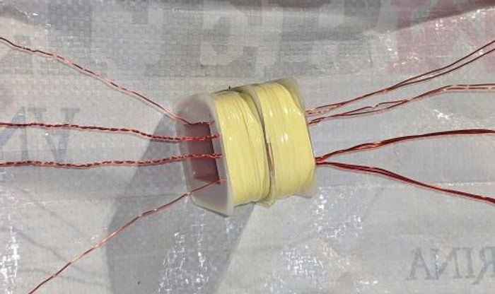
Terminations:
With eleven connections on this transformer, it was going to be difficult to attach leads to each and secure them to the coil. I decided to just run the magnet wire out to tie point strips. These strips can be connected to the rest of the circuit using Flag Spade electrical terminals. (see Fig 12 “Tie Point terminations”).
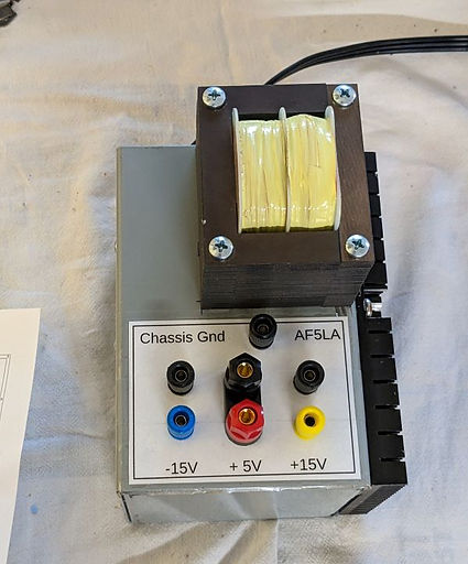
Finished Project: (Fig 15 Schematic)
NOTE 1: Circular Mils explained: It is the area in thousands of an inch² (Mils²), occupied by square box that will just touch the circumference of the wire diameter. (See Fig 5)
To calculate, cmil = Wire Diameter in Mils Squared. Example: 30ga single enamel magnet wire is 0.0108 diameter in inches. 0.0108 * 1000 = 10.8 Mils, 10.8 Squared is 116.64 cmil
[1] CWS Bytemark <https://www.cwsbytemark.com/index.php?main_page=index&cPath=206_284>
[2] EDCOR USA < https://edcorusa.com/collections/laminations>
[3] EDCOR USA < https://edcorusa.com/collections/coil-bobbins>
[4] Cosmo Corp. < http://www.cosmocorp.com/en/bcat-search3-1.cfm>
[5] U.S. Solid Manual Coil Winder NZ-1 < https://ussolid.com/u-s-solid-manual-coil-winder-nz-1-coil-winding-machine-w-counter.html?gad=1&gclid=CjwKCAjwvJyjBhApEiwAWz2nLQrZR_3YIeBugVIG8BrMijnAFdIAy2K3cxWf6VpANopRF7rD4zR3OhoCUbQQAvD_BwE>


Section Title
List Title
This is a Paragraph. Click on "Edit Text" or double click on the text box to start editing the content.
List Title
This is a Paragraph. Click on "Edit Text" or double click on the text box to start editing the content.
List Title
This is a Paragraph. Click on "Edit Text" or double click on the text box to start editing the content.
Section Title
Every website has a story, and your visitors want to hear yours. This space is a great opportunity to give a full background on who you are, what your team does and what your site has to offer. Double click on the text box to start editing your content and make sure to add all the relevant details you want site visitors to know.
If you’re a business, talk about how you started and share your professional journey. Explain your core values, your commitment to customers and how you stand out from the crowd. Add a photo, gallery or video for even more engagement.